Thursday, February 17, 2011

Powered by Radio Waves


In WWII, ally POWs invented some ingenious devices while imprisoned. One of the most resourceful and impressive of these was something called a crystal radio. Fairly straightforward and simple to make, these devices harnessed local materials using an impressive amount of understanding of scientific principles, and made them into a working radio set. While not always successful, these “foxhole” radios, as they were called, would pick up German and occasionally even British stations if they were carefully made. As impressive as anything else made by the POWs of the day, these foxhole radios are still made by Boy Scouts and hobbyists.

We chose this project to demonstrate electrical currents and radio waves. Our first attempt was met with limited success. However, after several tries, we were able to get a (faint but audible) radio signal. We ended up using a magnetic copper wire stretching over fifty feet as our antenna, which sacrificed historical accuracy, but it was nonetheless successful.


The first design we used was based off of the radio in a Make Magazine video. We were able to pick up static, but the signal was too weak to pick up actual stations. After a day or so of tooling with it, we decided to start from scratch, using the instructions and parts supplied in the Science Wiz Inventions kit. After some modifications to the original design (like adding a fifty-foot antenna) we were able to pick up fairly clear signals. The clearest we were able to pick up (Albany Magic 590 AM) turned out to be coming from a station 25 miles away from us, in Latham, NY.

Some other resources we used:

Here is a video of our radio in action, followed by explanation of its parts:


Parts of the Radio

Antenna - 50+ foot wire strand
Our antenna was fairly simple. We bought a length of magnetic copper wire, about fifty feet or so, and hung it around the entire house, starting in the mud room on the first floor and traveling up the stairs to the master bedroom on the second. The longer the antenna is, the clearer its signal seems to be. The antenna serves to convert electromagnetically radiated radio waves into electrical current, making them able to be conducted by the inductor.

Inductor - The coil of copper wire
We made out inductor out of about a hundred turns of copper wire wrapped around a cardboard toilet roll former. Our inductor serves alongside our variable capacitor as what is called a tuning circuit. Since the inductor conducts electricity, once the antenna converts the radio waves into electrical currents, the inductor can transmit the currents to the capacitor. However, since the inductor is coiled, the current must travel the coil, and thus travels slower than it would if the inductor was a straight piece of wire connected to the capacitor. The slower current allows the capacitor to tune to specific radio stations.


Variable Capacitor - The aluminum foil-covered tubes
Our capacitor was made by taking a long cardboard tube and wrapping smoothed aluminum foil around half of it. We then took a smaller piece of aluminum foil (again smoothed) and wrapped it around a wider piece of paper. Finally, the paper and aluminum foil were wrapped around the half of the cardboard tube covered in aluminum foil. This, once hooked up to the rest of the radio, serves as our variable capacitor, or tuning capacitor. This, when combined with the aforementioned inductor, creates a tuning circuit. The capacitor is designed to store electrical charge. However, it is only possible for charge to be stored in the spot that the aluminum foil wrapped around the paper, called the slider, overlaps with the foil on the tube. Moving the slider up and down can either increase or decrease the amount of charge stored in the capacitor. The capacitor allowed us to change which radio station was being picked up by changing the amount of electrical charge stored in the capacitor.


Diode - The germanium crystal OR "blued" razor blade and safety pin "cat's whisker"
In our different attempts at the radio, we ended up using two different diodes. Our first was a traditional foxhole diode using a razor blade and a “cat’s whisker” made from a safety pin and a sharpened pencil stub. The point of the pin was stuck into the end of the pencil through the exposed graphite (the "lead"). The safety pin was then attached to the base with a thumbtack and partially straightened so that the lead pencil tip touched the razor.  


Most directions call for a blade that had been “blued,” or given an oxidized coating to protect it against rust. You are able to blue a blade simply by heating it up in a flame of some sort. We tried a box cutter blade that had spots of rust (oxidation) on it, but couldn't get it to work. Then we built a second radio and used the germanium crystal (see below). After we got that to work, we substituted a razor blade from a scraper that was blued in the flame of our gas stove. Both the blued part and the "white" unheated lip of the razor worked to some extent. The white part produced loud static, but on the blued part we could just barely tune in a station.

For our second design, we used a germanium crystal diode that came in the kit. Both versions of the diode serve to force the signal to only travel forwards, thus converting it from alternating current to direct current. It also serves to filter out anything other than the strongest parts of the signal, called "peaks." This allows us to tune the signal to various stations using the capacitor and to convert the signal into sound.

The germanium diode works much better and is easier to use than the razor blade diode. (We later we went back to the first radio and got that one to work with the germanium diode as well.) Some sources we found state that moving the cat whisker on the razor blade is another way to tune the radio, but that needs to be verified.

Ground - The cold water pipe
Our ground was fairly simple. In both versions of the radio, we took a wire and attached it to the cold water pipe in our bathroom sink, making sure that the exposed metal wire at the end of the otherwise insulated wire touched the metal pipe. The ground, of course, allows the electrical current to flow through the radio. While exceedingly simple, it is perhaps one of the most important parts of the radio.


Speaker - piezoelectric earphone 
The most important, however, is doubtless the last part, the earphone. The earphone is a fairly basic piezoelectric earpiece, attached to the ground and the capacitor. Inside the earpiece (ours came in the kit, but you should be able to find one in a hobby store) is a copper wire coiled around a magnet. As the current flows through the coiled wire it creates an electromagnet. Also inside the earpiece is a transducer, or diaphragm, with iron embedded inside of it. As the current flows through the coil, it causes the magnet inside to grow stronger or weaker, depending on the peaks of the signal. Its attraction to the diaphragm also grows stronger or weaker. This causes the diaphragm to vibrate in accordance with the signal, producing sound vibrations.

(Thanks to Anthony for researching and writing up this post!)

Tuesday, February 1, 2011

Maxwell's Equations for Dummies


We are working on a post about our lab on radio waves that will be ready soon. In the meantime, I wanted to make a note of a website I found when looking for an explanation of Maxwell's Equations (mentioned in the "Joy of Science" lecture on electromagnetic radiation) that we could understand without the math. This explanation comes from a site called Irregular Webcomic, the creation of David Morgan-Mar, an astrophysicist and former science teacher in Australia.
Maxwell's equations are a set of four equations that describe the relations between electricity and magnetism. Written more neatly, they look like this:
To understand the mathematical notation here, you need to know vector calculus. I believe, however, that anyone can understand Maxwell's equations, and why they are so important and amazing, if they're explained clearly enough.
Morgan-Mar even spells out the connection between Maxwell's equations and radio waves:
From this breakthrough have come countless other discoveries about the nature of light, as well as its sibling electromagnetic waves: radio, microwaves, infrared and ultraviolet, x-rays, and gamma rays. All these forms of radiation are made of electric and magnetic fields, moving through space at the speed of light, exactly as described by Maxwell's equations. We now know that radio waves, for example, can be generated by switching an electric current on and off at high speed. The electrons in the wires wiggle back and forth, creating wiggling electric fields, which create magnetic fields, and so on - the overall effect being radio waves. And radio waves in turn wiggle the electrons in your radio or TV antenna, creating electric currents that various electric circuits turn back into sound and pictures. 
I enjoyed browsing around Morgan-Mar's site, including his pages celebrating LEGO and Star Trek. I suggest you take a look.

Update: My kids tell me that everyone on the Internet has already heard of Irregular Webcomic except me. Ah well.

Thursday, January 13, 2011

Bending Light


Lecture 14 of The Joy of Science describes the properties of Electromagnetic Radiation, including light. Light waves can be made to bend as they pass through substances of different densities, like air and water.

One experiment I always wanted to try was using a stream of water like a fiber optic cable to bend light. We saw a demonstration of this at the Corning Museum of Glass last summer. The exhibit at Corning got cool effects by varying the stream of water from a steady flow to drops.

Our version was made using an empty soda bottle and a laser pointer. It works best at night, or in a room that can be darkened. Here is what we did:

Materials:

laser pointer (I got a couple different kinds from the supermarket, about $6 each)
stand for laser pointer (we tried poking it through a foam cup and laying it on a stack of coasters) 
rubber band
clear empty soda bottle with cap
water
milk
permanent marker
metal skewer
flame
masking tape
sink

  1. Fill the bottle with water and put a few drops of milk in to make it slightly cloudy. You can also try mixing in a little powdered milk or corn starch.
  2. Wrap the rubber band around the laser pointer so it is pressing the "on" button continuously.
  3. Set up the laser pointer so it is lying horizontally about 3 or 4 inches from the surface of the counter. Put it next to the bottle and adjust until you see the line of light passing through the milky water.
  4. With the marker, make a dot where the light beam touches the far side of the bottle. Pour out all the water.
  5. Heat the metal skewer in the flame (such as a stove burner) until it is very hot. Use the tip to melt a small hole in the soda bottle at the dot.
  6. Cover the hole with a piece of masking tape. Put the cap on tight.
  7. Fill the bottle again with milky water. Place it on the counter next to the sink. Set up the laser pointer so it is aimed through the bottle at the hole. Take the tape off to see if the light hits the hole. (The water won't come out until you loosen the cap -- try it!)
  8. When everything's arranged, loosen the cap until you get a stream of water pouring into the sink. Adjust the light or walk around the bottle until you can see the light in the curved stream of water.


What's Happening?

The laser beam is "trapped" inside the water because of Total Internal Reflection. As the light tries to pass from the more-dense water to the less-dense air, it bends. (This is called refraction.) At a certain point the light bends so much that it is bounces off the surface of the water. (This is called reflection.) In the narrow column of water, the light wave continues bouncing off the boundaries of the stream of water but cannot pass through into the air.

The same principle applies with a piece of glass or plastic fiber optic cable. We have some lying around somewhere. I'd like to try using it in an art project, but with LED bulbs instead of lasers....

Monday, December 27, 2010

The No-Frog Battery


In Lecture 12 of The Joy of Science, Prof. Robert Hazen tells the story of the first electric battery. In 1799, Alessandro Volta was the first person to devise a way to chemically generate electricity without the use of frogs. I decided to try this experiment at home.

Luigi Galvani and his wife Lucia discovered that dissecting frog legs
with a scapel near an electrostatic generator caused the muscles to jump.

We had tried to make a Lemon Battery back when we were doing chemistry. We were not successful. I was all ready to go out and buy a bag of lemons and try again, when I came upon this Tiny Lemon Battery Instructable. The author shows many different ways to create what one commenter dubbed "nano-batteries" using the bare minimum of materials and only a few drops of lemon juice. Since I had a bottle of lemon juice in the fridge, and the other materials were easily scrounged from our science and art supplies, we were able to make a few different types of batteries in the course of a morning -- two of which actually worked!

Method One: Copper and Aluminum Foil Batteries


Materials

copper foil (available in craft stores)
aluminum foil (from the supermarket)
facial tissue (Kleenex)
multimeter or voltmeter
disposable plate (to work on)
dish soap or lemon juice

  1. Cut a piece of copper foil about 1 inch by 2 inches.
  2. Separate the tissue into layers. Cut a piece about 1 inch by 3 inches.
  3. Cut a piece of aluminum foil about 2 inches square.
  4. Layer the materials so that the aluminum foil is on the bottom, the tissue is in the middle, and the copper is on top. Fold the aluminum foil so that the edges wrap around the tissue and copper foil as shown above. This is your battery.
  5. Place the battery on a plate. Soak the paper with either dish soap or lemon juice. (We tried one of each.)
  6. With your voltmeter, measure the voltage generated by placing one terminal on the copper and one on the aluminum. We got up to half a volt of electricity from our primitive Galvanic cell batteries.

Method Two: Copper and Zinc Wire Battery

Materials
2 inch long piece of zinc-plated steel wire ("galvanized" picture-hanging wire works well)
4 inch long piece of uncoated copper wire, as thin as possible
a layer of Kleenex (see above)
disposable plate
lemon juice or dish soap

  1. Cut a piece of tissue about 1 1/2 inches long and 1/2 inch wide.
  2. Wrap the tissue layer around the steel wire, leaving the ends uncovered.
  3. Coil the copper wire around the tissue, being sure not to touch the steel wire inside. Make the coils as close together as possible without overlapping. 
  4. Soak the paper in lemon juice or soap as above and measure the voltage!
The Instructables page has directions for several variations, which include making several batteries and attaching them in series to light an LED, and flower and animal "sculptures" which use lemon juice to light up attached LEDs using the same techniques. One variation which we tried but did not (yet) get to work was to make tiny batteries from coils of wire inside lemon juice-filled drinking straws sealed with hot glue. Although the cells we made looked right, we could measure no voltage from them. We'll write an update post when we've got a few more designs to show off!

Wednesday, December 15, 2010

Second Law of Thermodynamics -- Keeping Butter Cool with Evaporation

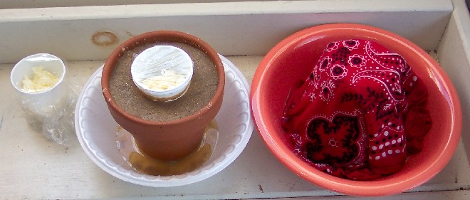
The setup. Left to right: the control, Anthony's experiment (The cup of butter was kept in wet sand,) and John's experiment, (The butter was put in a bowl of water, and covered by a ceramic pot and a cloth.)

After watching The Joy of Science lecture about the Second Law of Thermodynamics, I decided to spend a week focusing on entropy. Entropy is a concept that has always interested me, although I don't understand very well. I first read about it in a short story by Thomas Pynchon, and then ran into it again when I saw Tom Stoppard's play Arcadia. But despite its interest for writers, it doesn't seem to have inspired a lot of popular science videos we could watch. The only mention I could find in the archives of what is now my favorite science show, NOVA, was a show about Absolute Zero. Luckily, this topic proved to be interesting in its own right.
The Teachers Guide for NOVA programs often contain good hands-on science activities. In this case, however, I thought the activity -- using a thermometer to calibrate a homemade thermometer -- was a tad lame. But a mention in the show about the discovery that evaporating chemicals could be used to produce refrigeration did catch my attention. I started Googling for safe classroom-type activities the kids and I could do to recreate the 1823 experiment by Michael Faraday, but perhaps without the potentially explosive chlorine.

Taking the temperature of butter in a Butter Keeper
And then it occurred to me that I could use the concept of a Butter Keeper -- a porous terracotta holder that keeps butter cool through water evaporation -- to achieve the same purpose. (Ironically, the type of Butter Keeper which inspired this activity actually keeps the butter cool by sealing out air, not by cooling it!)

We looked at some different types of evaporative coolers, including a similar metallic evaporative cooler invented by a student when she was in high school. We then gathered some materials and tried making our own. Although we did get some cooling, the Butter Keeper works is most effective in hot, dry climates. Here are the directions for our experiments:

The materials.

Materials:
  • room-temperature butter (we made a bowl of butter by whipping heavy cream; you could also soften some store-bought butter)
  • plastic wrap
  • digital food thermometer (about $15)
  • terracotta flower pots
  • terracotta flower pot dishes
  • disposable bowls and cups
  • sand
  • cloth (we used a bandana)
  • water
  1. Fill a small disposable cup with softened butter. Cover with plastic wrap
  2. Use the food thermometer to punch a hole through the plastic wrap and take the temperature of the butter.
  3. Use the materials on hand to design and assemble a Butter Keeper that will hold the cup of butter. The Butter Keeper should hold and absorb for an extended period. See the photos for ideas.
  4. Place the cup of butter in the Butter Keeper. Place another cup of butter next to it as a control. Check the temperature of both cups at regular intervals to see whether the butter in the Butter Keeper is cooler than the butter sitting outside at room temperature.


What We Did:

John built one using a cloth to wick up water from a dish holding the terracotta pot. This design was apparently used in Great Britain and Australia in the 20th century.

The preparation of John's experiment. The cloth wicked the water up over the pot to keep it wet.

John's experiment.
Anthony used a smaller container set into a terra cotta pot filled with sand and then dampened. That version comes from Africa, where it is known as a zeer, and is used to keep produce fresh in areas where electricity is unavailable.
The setup for Anthony's experiment.
The sand in this experiment serves the same purpose as the cloth in John's.
 What Happened: We assembled the Butter Keepers and set them out on a bench, next to an unprotected cup of butter. We kept the pots wet by periodically refilling the bowls as needed. When we started, the butter was 65 degrees. Within a few hours it had decreased to 62, while the control cup was at 70. While not a gigantic difference, it does show a noticeable drop in temperate, from both the un-refrigerated control and the actual room temperature. After a few days the butter did begin to smell bad, and we ended the experiment. Note: Our first thermometer, from Wal-Mart, died soon after we started. We bought a slightly better version from an upscale cooking equipment store, which worked fine.

Friday, December 3, 2010

Our Galileoscope


In Lecture 3 of The Joy of Science, Prof. Hazen talks about how Galileo used his telescope to explore the heavens, and was the first to observe the craters of the moon, sunspots, and Jupiter's moons. (In the process upsetting medieval European society by suggesting that the celestial bodies were not "perfect.")

We happened to have on hand a reproduction of Galileo's telescope, the Galileoscope. This inexpensive instrument was designed for student use during the International Year of Astronomy in 2009. Although it claims to have decent lenses, it is very lightweight and doesn't come with a stand, which makes it hard to use. We had never really used it, but this seemed like a good time to try again.

First, we set up the telescope for projecting sunspots on a piece of paper. (NEVER point a telescope at the sun!) Unfortunately, after checking SpaceWeather.com, we found that we had picked a day that the sun really did have no spots! However, we were able to see the disc of the sun. We will have to try this experiment again.


A few weeks later on a particularly cool crisp night, I noticed that Jupiter was clearly visible near the almost-full moon. I set up the Galileoscope on our front lawn. The moon and Jupiter were so bright that they could be observed even with the streetlights shining. I had never seen the moons of Jupiter through a telescope before, but they were clearly visible in the Galileoscope. The four Medici moons were lined up horizontally, three to the left of Jupiter and one to the right. About a month later, with the conditions almost the same, I pulled the telescope out and took another look. This time the line of moons was tilted down towards the left, and there were two moons on either side of Jupiter.


I was unable to take any photos of Jupiter with my little digital camera. (The image above is from Wikipedia.) So instead I pointed the Galileoscope at the moon and took some photos of it. The craters of the moon can be seen along the right edge. To get the photo, I held the set the camera for landscape (so the focus would be infinity) and held the lens a little bit away from the eyepiece. I lined up the image of the moon on the screen and then shot the photo. Pretty nice, right?


We also watched Bertoldt Brecht's play Galileo, which I have seen performed live. It does a good job of showing the conflict between the scientist and the Church. A good book for younger kids, which we read many years ago is Starry Messenger by Peter Sis. That is the title of a work by Galileo, which was part of a museum exhibit we saw called A Very Liquid Heaven. I was very impressed with the large meteorite (below) which was part of the combination art and science exhibit.

Tuesday, November 30, 2010

Magnets and Declination

In The Joy of Science, Lesson 11: Magnetism and Static Electricity, Robert Hazen explains that the Earth is itself a giant magnet. In the Northern Hemisphere, the north end of a compass will point down towards the magnetic North Pole. He described an experiment by Robert Norman in his book The Newe Attractive which showed the declination by floating a magnetized needle in a piece of cork in a container of water. By shaving away the cork, Norman got the needle to float below the water's surface so that it's dip toward the Pole could be seen.

We tried to recreate Norman's experiment from Hazen's description using a needle and a straightened paper clip as the magnetic pointers, and real and artificial cork and pieces of a Styrofoam cup as the floatation device.We did get the needle to point on a north-south axis. But it was hard to tell if the needle dipped, because the angle would change depending on where the cork was.

There's another description of Norman's experiment at Practical Physics. And Safe and Simple Electrical Experiments (viewable through Google Books) gives some alternate ways of observing the declination of the needle. You can find the magnetic declination for your position at NOAA's Geophysical Data Center.