Sunday, August 28, 2011
More Integrated Science
The Ceceri family will be continuing our study of Integrated Science this year, but with one less student. John III is now off at Rochester Institute of Technology, where he is in the Interactive Games and Media program.
As a going-away present, I made him this great fish tank, using genetically-modified fluorescent GloFish. Watch the video to see what happens when you turn on a blacklight!
The mini-aquarium I put together is a project I've written about before on Home Biology. Here are the instructions, which I ran on GeekMom last week.
Keep watching this space for more labs related to the Joy of Science video series. We'll also be trying out some electronics projects as I work on a new children's activity book about robotics. I'm looking forward to another fun year!
Friday, June 17, 2011
Foam Plate Speakers

For science this week, we decided to experiment more with audio devices. (The episode of The Joy of Science we had just watched was about properties of matter, including magnetism, and mentioned that speakers worked because magnets changed shaped.) Since we had already built a radio, this time we built a speaker. The speaker was much easier to make and much less elaborate than the radio, and we were able to have it working in about a half-hour. Despite requiring some fine-tuning, we were able to get it to work very well.
This simple and elegant project was designed by Jose Pino. You can see it being made in this Make Magazine YouTube tutorial.
We didn't test our speaker out with our foxhole radio, because the volume is so low on both devices. Instead we used an mp3 player. But we plan to try our homemade radio with the speaker sometime in the future.
 Materials:
A foam plate
Two strips of paper
Two business cards (we just cut an index card in half for this)
Tape
A hot glue gun
Magnetic copper wire (Jose Pino recommends using AWG 32)
Neodymium magnets
An audio plug
A piece of cardboard
1. We started by rolling one of the strips of paper over the magnets. We then taped the roll closed, being careful not to tape it to the magnets.
2. Next, we rolled the other strip of paper around the first strip, and taped it closed. We cut this strip a little less wide than the first. This made the outer strip stick out a bit more than the inner one.
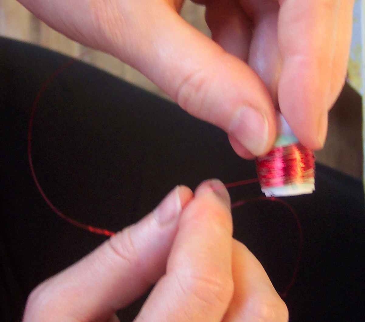 3. Keeping the magnet inside the tubes of paper, we coiled the copper wire around it, using about 50 turns. Leave a few inches of copper wire uncoiled on each end.
4. We then pulled the magnet out of our paper, along with the inner strip (we made it wider so that it would be easier to pull out.)
5. Discarding the inner strip, we then hot-glued the outer to the bottom of the foam plate, being careful to have it in the center.
6. Next, we hot-glued the magnet to the cardboard. After that, we folded the business cards in an accordion shape, we glued them to the bottom of the plate, one on each side of the coil. We then put hot glue on the bottoms of the cards, and glued them to the cardboard base, making sure that the coil would go over the magnet.
7. We tested the wires by touching the ends to either end of a battery. This is what happened:

8. To connect our speaker to a sound system, we needed an audio plug. We got one by cutting the end off a cheap set of earbuds from the dollar store. FIrst we had to sand off the coating from each end of the copper coil wire and strip the rubber insulation from the ends of the audio plug. Because the earbuds were stereo, we needed to connect one wire from each earbud to each of the copper coil wires in order to hear both sides. (We're not sure that worked well, though.)
9. Finally, we plugged the audio wire into a music device. We found that MP3 players worked the best.
How it Works:
The speakers operate largely on the same principle as the piezoelectric earpiece we used in our radio experiment. The coil serves as an electromagnet. It receives electrical currents from the audio plug, which gives it either a stronger or weaker attraction to the magnets. This causes the foam plate to bounce up and down, creating sound vibrations.
Monday, May 23, 2011
More Plasma Fun
We had so much fun playing with our plasma ball, we decided to try making some plasma of our own! According to YouTube, this is easy to do if you have (a) a microwave and (b) a grape. This experiment was about the most exciting thing we have ever tried in our kitchen. Here's how to do it:


- large juicy grape
- knife
- microwave-safe plate
- microwave-safe tall heavy glass, preferably tapered (like a beer or coke glass)
- Cut a grape in half across the middle. Take one half and cut the long way, leaving a bit of skin to hold the halves together.
- Open up the halves and place grape on a small plate. Remove the rotating turntable in the microwave. Place the plate in the microwave.
- Turn off the lights. Set the microwave for 5 seconds (but stand by to hit "Stop" when needed). You should see sparks and a puff of “flame.” That is the plasma.

Here's something even cooler: To make a kind of Jacob's Ladder, cover the grape with the glass. Make sure the glass is sturdy, or it may break! Set the microwave for 5 seconds (but stand by to hit "Stop" when needed). You should see blobs of plasma rising in the glass over and over.
Here's an explanation of how a microwave creates plasma from Naked Scientists:
A microwave oven heats up food using microwaves - these are electomagnetic waves that cause electric current to move back and forth between the two halves of the grape. This current is concentrated in the piece of skin between the two, which will heat up and dry out. The current then has to move through the air, creating a spark.
The spark is created when the electric field rips electrons off atoms. These can then move freely and carry electric current. A gas with free electrons and positive ions is also known as a plasma. This plasma conducts electricity and can absorb microwaves. Sometimes the plasma gets big enough to absorb enough microwaves to keep growing.
And from Physics Forums:
There's two clean grape surfaces that are separated by a fraction of a millimeter near the corner of an air wedge. The electric field between the grape portions at the tip of the wedge is large enough to cause breakdown in the air gap, making a plasma ball there.
Thursday, May 5, 2011
Plasma: The Fourth State of Matter

This week's episode of The Joy of Science was about States of Matter. Most people are familiar with three: solid, liquid, and gas. But there is a fourth state of matter: plasma.
Plasma is a gas-like field made up of charged atomic particles – negative electrons and positive ions (atoms which have lost some of their electrons, and so have an excess of positrons). As they move, these particles generate electricity and magnetic fields. Plasma requires low pressure and extremely high temperatures. On Earth, plasma only occurs naturally in the form of lightning, polar auroras, and extremely hot flames. However, plasma is actually the most common state of matter in the universe, since it makes up stars and other celestial bodies, as well as the space in between.
Plasma was first identified in 1879 by Sir William Crookes, who called it "radiant matter." It can be created artificially by running an alternating electric current through certain types of gas in vacuum tubes. This “knocks electrons” off the atoms inside.
In this experiment, we decided to use a plasma globe to observe some properties of plasma. A plasma globe is a type of lamp that you can buy in a novelty shop, museum gift shop, or through a science supply house. Inside the glass bulb of the plasma globe is a Tesla coil. This creates a plasma field of electrically charged particles, which look like small tendrils of lightning.

When we turned the plasma globe on and touched the glass, the tendrils of lightning concentrated at the spot that was touched. Touching it in more than one place at the same time created several points of concentration. Our plasma globe also had a setting that made it react to sound waves. We put mp3 speakers next to it and watched it flick on and off in relation to the music. Interestingly, it was more affected by frequency (how high or low the note was) than to volume. It reacted very strongly to particular notes and not at all to others. This reminded us of seeing the band ArcAttack at Maker Faire NY. ArcAttack creates music using giant Tesla coil-driven plasma arc speakers.
The first experiment we did was to hold different kinds of unplugged light bulbs near the globe. As described on the Plasma Ball experiments page on the Wonders of Science website from the University of Wisconsin, some electrons from inside the globe travel through the glass to the light bulbs.

Inside the bulbs are gas molecules. In fluourescent bulbs, molecules of mercury vapor become excited by the energy of the charged particles bombarding them from the plasma field. Electrons in the mercury atoms make a quantum jump to a higher energy level (or shell) around the atom's nucleus. When they return to their previous energy level, the extra energy is given off in the form of light. When they are plugged in, fluourescent tubes also operate by creating plasma fields out of the mercury gas.
We got good results with fluorescent and neon lights, above and in the videos below. We also tested Halogen and Xenon bulbs, but were unsuccessful.
Our second experiment was more elaborate. First, we balanced a penny on the top of the globe. Next, we took another penny, and close to the penny balanced on the dome, but not touching it. As in the first experiment, some electrons from the plasma field traveled through glass and were carried by the penny on top as an electrical current. The penny was able to carry a current because they are made out of a conductive material, copper. Holding a second penny above the first drew the electricity throught the air, creating a tiny spark. You can just barely see the spark in the photo below; in the video you can see and hear the tiny crackle as the pennies spark.

We also tried sending sparks to our fingers. We found that, if we weren’t grounded, we could send a spark from the penny to one of our fingers without feeling a shock!
Stay tuned for more exciting plasma experiments in the second part of our report on States of Matter!
Monday, April 25, 2011
Isolating DNA -- a long polymer chain

Oswald Avery received the Nobel Prize in 1943 for confirming that DNA carried genetic information. Each strand of human DNA is divided into 23 pairs of chromosones, which in turn contain hundreds or thousands of genes. Genes record information in the form of chemical codes about how to build the proteins and other molecules which make up living organisms.
DNA is one of the longest type of polymers, or chains of molecules. Strands of human DNA are 6 feet long. In 1950, scientist Rosalind Franklin used X-ray crystallography to find that DNA is made up of two long polymers, or chains of molecules, twisted into a shape called a double helix. In 1953, James Watson and Francis Crick discovered that the strands were connected by crossbars, like a ladder. They won the Nobel Prize in 1962 for uncovering DNA’s structure.
Isopropyl (rubbing) alcohol (70 or 91 percent)
Clear plastic cups
Plastic spoons
Small plate (preferably disposible)
Drinking water
Salt
Dish soap
Blue food coloring (optional)

Step 1: Chill the alcohol
Place the bottle of alcohol in the freezer to chill while preparing the next steps. (Do not leave in long enough to freeze!)
Step 2: Gather the DNA
In the plastic cup, mix ¼ teaspoon of salt in 1/4 cup of water. Swish the salt water around in your mouth for a minute, making sure it reaches the inside of your cheeks. Spit all the water back in the cup. Do not swallow! (If you prefer, you can also use Gatorade, which is sweeter.)
Cells from the inside of your cheek mix with the salt water and are carried away when you spit. Above is a photograph of cheek cells under a microscope. You can see the nucleus inside each cell.

Step 3: Release the DNA from your cheek cells
Put a drop of dish soap on the plate. Touch the spoon to the soap, and then dip it in the cup of salt water. Gently stir once or twice. Cells are contained within membranes that are made up of fats. The soap solution breaks down the fat molecules, just like soap breaks down grease on your dishes, and releases the contents of the cell.


Step 4: Add the alcohol
Remove the alcohol from the freezer. Pour about a quarter of a cup into a second plastic cup. If desired, add a drop of blue food coloring to make the alcohol easier to see. Stir until evenly mixed. Take the salt water cup and tilt to one side. Hold the cup of alcohol up so that the lip touches the tilted cup. SLOWLY pour a little alcohol down the inside of the cup so that it floats on top of the salt water without mixing. Continue until there is about an eighth of an inch of alcohol on top of the salt water.

Step 5: Watch the DNA strands appear
Wait a few minutes and you will see long strands or clumps of a sticky white substance start to come together in the alcohol layer. This is the DNA from thousands of cheek cells in the salt water. The DNA cannot dissolve in the chilled alcohol, so it precipitates out (comes out of solution as a solid).
Variation: If you want to remove the DNA to look at it through a microscope, dip a toothpick into the alcohol layer and twirl it to gather up the sticky DNA. Place on a glass microscope slide. You can also save the DNA in a small clear container with a little extra salt water. Keep tightly covered.
More information:
http://tang.skidmore.edu/pac/mtm/DNA/index.html
www.nespal.org/oziasakinslab/edout/AnimalDNAExtraction.pdf
http://www.vampirewear.com/dna.html
http://nature.ca/genome/05/051/0511/0511_m204_e.cfm
http://www.californiasciencecenter.org/Education/GroupPrograms/HomeSchool/docs/DNA.pdf
Tuesday, April 12, 2011
Splitting Saltwater
Last week we watched an episode of The Joy of Science dealing with elements that have an affinity for one another, like sodium and chlorine. In the great Theo Gray book Mad Science, he shows that combining sodium and chlorine to make your own salt results in quite a bang.I was looking for other interesting sodium-related YouTube videos when we came across one that showed a cool way to split salt into its component elements.
Above you can see our version of the experiment. What we did is explained below.

Saltwater Electrolysis
Materials:
-Salt
-One 9-volt battery
-Two spoons
-A medium-sized glass bowl

Steps:
1. Fill the bowl with warm tap water, and stir in a spoonful or so of the salt.
2. Place the two spoons in the water, being careful not to let the two spoons touch each other.
3. Hold the ends of the two spoons to the battery connectors, one spoon on each connector.

4. Within a few seconds, you should see tiny bubbles coming off of the spoons. You will also notice what looks like smoke coming off the water.
5. After holding them in a minute or so, you should be able to see the water begin to turn murky yellow.
6. After several minutes, the water starts to turn dark green.

Here is an explanation of what's happening (from the NASA Aquarius website):
In chemistry, electrolysis is a method of separating bonded elements and compounds by passing an electric current through them. An ionic compound, in this case salt, is dissolved with an appropriate solvent, such as water, so that its ions are available in the liquid. An electrical current is applied between a pair of inert electrodes immersed in the liquid. The negatively charged electrode is called the cathode, and the positively charged one the anode. Each electrode attracts ions which are of the opposite charge. Therefore, positively charged ions (called cations) move towards the cathode, while negatively charged ions (termed anions) move toward the anode. The energy required to separate the ions, and cause them to gather at the respective electrodes, is provided by an electrical power supply. At the probes, electrons are absorbed or released by the ions, forming a collection of the desired element or compound.According toWikipedia, this is the formula for the chemical reaction taking place:
One important use of electrolysis is to produce hydrogen. The reaction that occurs is 2H2O(aq) → 2H2(g) + O2(g). This has been suggested as a way of shifting society towards using hydrogen as an energy carrier for powering electric motors and internal combustion engines. Electrolysis of water can be achieved in a simple hands-on project, where electricity from a battery is passed through a cup of water (in practice a saltwater solution or other electrolyte will need to be used otherwise no result will be observed). Electrolysis of an aqueous solution of table salt (NaCl, or sodium chloride) produces aqueous sodium hydroxide and chlorine, although usually only in minute amounts. NaCl(aq) can be reliably electrolysed to produce hydrogen. Hydrogen gas will be seen to bubble up at the cathode, and chlorine gas will bubble at the anode.
2 NaCl + 2 H2O → Cl2 + H2 + 2 NaOH
That means, two sodium chloride molecules (which is the salt) plus two dihydrogen monoxide molecules (also known as water) becomes one chlorine molecule, one hydrogen molecule, and two molecules of sodium hydroxide (which is also known as lye). So in our experiment, the bubbles were hydrogen, the "smoke" coming off the water was chlorine gas, and the yellow color of the water was the sodium, in the form of lye.
Friday, April 1, 2011
Observing Energy Levels of Electrons Using a Cereal Box

In our most recent episode of The Joy of Science, Dr. Hazen describes observing energy levels of electrons and atoms using a Spectroscope. So, for science this week, we decided to make a Spectroscope out of a cereal box and diffraction grating glasses. We used it to look at different light sources.
Spectroscopy is the study of light-matter intersections. By using a spectroscope, scientists make a record of the light intensity over a range of wavelengths. Each element produces its own spectrum, and many new elements were discovered by this method. Astronomers use spectroscopy to figure out the composition of stars and whether they are moving towards or away from the earth.
The way spectroscopes work is by breaking light up into its different wavelengths. The light can be viewed through a filter (as we did in this version) or reflected off an object's surface (as we did in a version we made a few years ago; see below).
 |
| This photo was shot using the diffraction grating glasses before we taped them to the Spectroscope. |

For our diffraction grating, we took a pair of cardboard holographic glasses and cut them in half. We made two Spectroscopes, so we used one half for each one.
Next we took the cereal box, placed the diffraction grating on top, and outlined it using a sharpie. We made marks to indicate where the actual lens was. Then we opened the flaps and cut a hole the size of the lens in the cereal box.
We then taped the cereal box flaps closed and taped the grating over the opening.

On the opposite side of the box from the grating, we made a mark and cut a very narrow slit. During our first attempt at the spectroscope, we made the slit wider than recommended. We fixed this by taping a piece of card stock over the slit and cutting through that. However, a different set of directions suggested using a wider slit, so we also tried taking photos with the original slit as well.
 | |
| Fluorescent light, using wider slit. |
After completing it, we took some photos by holding the camera up to the grating, and pointing the Spectroscope towards a light. The result was the photo shown at the top of this post.
 |
| Detail of fluourescent light spectrum |
Here is a cropped version of the photo above, showing the bright lines of higher intensity at different wavelengths. Scientists use this kind of spectrum to analyze what elements are present in a light source. Our grating was not as high a resolution as a real Spectroscope, so it was harder to use. Our spectrum is more an approximation.
For more precision, you can try the directions for a homemade high-resolution Spectroscope from Simon Field at SciToys.com. A few years ago, we made his version of a Spectroscope using an old DVD. (It's also in his book, Gonzo Gizmos: Projects & Devices to Channel Your Inner Geek.)
Here's a site with really nice photos taken with a cereal box/CD type spectroscope.
Monday, March 7, 2011
Proving Atoms Exist with Brownian Motion
In 60 BC, the Roman poet Lucretius published a poem entitled De rerum natura, or On the Nature of Things. Its contents were mostly philosophical, focusing on themes of life, death, love, the soul, and such. However, the first two sections of the six-book poem were focused on a very different subject matter: atoms. The poem read:
“Observe what happens when sunbeams are admitted into a building and shed light on its shadowy places. You will see a multitude of tiny particles mingling in a multitude of ways . . . their dancing is an actual indication of underlying movements of matter that are hidden from our sight. It originates with the atoms which move of themselves [i.e., spontaneously]. Then those small compound bodies that are least removed from the impetus of the atoms are set in motion by the impact of their invisible blows and in turn cannon against slightly larger bodies. So the movement mounts up from the atoms and gradually emerges to the level of our senses, so that those bodies are in motion that we see in sunbeams, moved by blows that remain invisible.”This is a phenomenon called “Brownian Motion,” named after Botanist Robert Brown. Although it was Albert Einstein that finally described the physics behind this, it was named after Brown because of his being the first to test this theory by observing pollen grains bouncing off of water molecules. But it was ultimately Einstein who brought this to the attention of the physics community, and in doing so, proving the existence of what we now think of as atoms and molecules.
We decided to reproduce Brown’s experiment, adapting directions from Dave Walker.

What you need:
- student microscope with 200X or 400X magnification
- milk (we used 2%)
- microscope slides and coverslips
- thin needle or wire
- water (preferably distilled, although we used tap water)
- Vaseline petroleum jelly (optional)
1. Place a very small drop of water in the middle of the slide (use a dropper).
2. Dip the needle in the milk, then dip and stir in the water drop. We picked up a drop in the eye of the needle and stirred it with the needle almost flat in the water drop.
3. Gently lower the coverslip onto the diluted milk drop.
4. Make sure no water is near the edge of the cover slip. This is important to ensure you observe Brownian motion and not liquid movement caused by evaporation).
5. Optional: To make a slide that lasts longer, seal the coverslip on with a thin line of Vaseline to minimize evaporation.
 |
| Still photo of fat molecules taken with standard microscope and point-and-shoot camera. |
We tried this experiment with both our computer microscope and our standard microscope. Although we were unable to get decent pictures with either microscope, we were able to see decent results with the basic microscope.
We placed a droplet of water on a glass slide, and then, using a pin, we placed a smaller droplet of milk (we used 2% instead of whole) inside the water. We then placed a coverslip over the droplet, and sealed it with vasoline. The first few times we did this, we were unable to observe, or even locate the water droplet with our computerized microscope. However, after a few tries, we found that making adjustments to the experiment (such as not using vasoline and placing smaller droplets on the slide) were effective, allowing us to at least see the water. Switching from the computerized microscope to our lower-tech but more high-powered microscope produced much more positive results. The higher magnification allowed us to actually observe the Brownian Motion of the milk fat particles bouncing off the water molecules.
We also decided to test a simplified version of Brown’s experiment by dropping food coloring into a large bowl of water. While this was not as precise as the milk experiment, observing the cigarette smoke-like movements of the dye was more effective at demonstrating Brownian Motion. Above, you can see a video of a similar experiment, conducted by GeekMom writer Kay Holt and her son Bastian.
Other resources:
Wikipedia
Einstein Year
University of Virginia
Discover Magazine
Thursday, February 17, 2011
Powered by Radio Waves

In WWII, ally POWs invented some ingenious devices while imprisoned. One of the most resourceful and impressive of these was something called a crystal radio. Fairly straightforward and simple to make, these devices harnessed local materials using an impressive amount of understanding of scientific principles, and made them into a working radio set. While not always successful, these “foxhole” radios, as they were called, would pick up German and occasionally even British stations if they were carefully made. As impressive as anything else made by the POWs of the day, these foxhole radios are still made by Boy Scouts and hobbyists.
We chose this project to demonstrate electrical currents and radio waves. Our first attempt was met with limited success. However, after several tries, we were able to get a (faint but audible) radio signal. We ended up using a magnetic copper wire stretching over fifty feet as our antenna, which sacrificed historical accuracy, but it was nonetheless successful.

The first design we used was based off of the radio in a Make Magazine video. We were able to pick up static, but the signal was too weak to pick up actual stations. After a day or so of tooling with it, we decided to start from scratch, using the instructions and parts supplied in the Science Wiz Inventions kit. After some modifications to the original design (like adding a fifty-foot antenna) we were able to pick up fairly clear signals. The clearest we were able to pick up (Albany Magic 590 AM) turned out to be coming from a station 25 miles away from us, in Latham, NY.
Some other resources we used:
- MAKE Magazine's Foxhole Radio project with video and PDF plans
- The site SciToys offers several versions of increasing difficulty.
- YouTube has many videos of foxhole radios, including this one of a Tunable Foxhole Radio built by 10-year-old based on these plans from Gizmodo
- A project to make radios with fourth-graders, including printable guides for building
- The website Crystal Radio has lots of information, including a page to help you trouble shoot and test the parts of your radio.
Here is a video of our radio in action, followed by explanation of its parts:
Parts of the Radio

Our antenna was fairly simple. We bought a length of magnetic copper wire, about fifty feet or so, and hung it around the entire house, starting in the mud room on the first floor and traveling up the stairs to the master bedroom on the second. The longer the antenna is, the clearer its signal seems to be. The antenna serves to convert electromagnetically radiated radio waves into electrical current, making them able to be conducted by the inductor.

We made out inductor out of about a hundred turns of copper wire wrapped around a cardboard toilet roll former. Our inductor serves alongside our variable capacitor as what is called a tuning circuit. Since the inductor conducts electricity, once the antenna converts the radio waves into electrical currents, the inductor can transmit the currents to the capacitor. However, since the inductor is coiled, the current must travel the coil, and thus travels slower than it would if the inductor was a straight piece of wire connected to the capacitor. The slower current allows the capacitor to tune to specific radio stations.

Variable Capacitor - The aluminum foil-covered tubes
Our capacitor was made by taking a long cardboard tube and wrapping smoothed aluminum foil around half of it. We then took a smaller piece of aluminum foil (again smoothed) and wrapped it around a wider piece of paper. Finally, the paper and aluminum foil were wrapped around the half of the cardboard tube covered in aluminum foil. This, once hooked up to the rest of the radio, serves as our variable capacitor, or tuning capacitor. This, when combined with the aforementioned inductor, creates a tuning circuit. The capacitor is designed to store electrical charge. However, it is only possible for charge to be stored in the spot that the aluminum foil wrapped around the paper, called the slider, overlaps with the foil on the tube. Moving the slider up and down can either increase or decrease the amount of charge stored in the capacitor. The capacitor allowed us to change which radio station was being picked up by changing the amount of electrical charge stored in the capacitor.

Diode - The germanium crystal OR "blued" razor blade and safety pin "cat's whisker"
In our different attempts at the radio, we ended up using two different diodes. Our first was a traditional foxhole diode using a razor blade and a “cat’s whisker” made from a safety pin and a sharpened pencil stub. The point of the pin was stuck into the end of the pencil through the exposed graphite (the "lead"). The safety pin was then attached to the base with a thumbtack and partially straightened so that the lead pencil tip touched the razor.
Most directions call for a blade that had been “blued,” or given an oxidized coating to protect it against rust. You are able to blue a blade simply by heating it up in a flame of some sort. We tried a box cutter blade that had spots of rust (oxidation) on it, but couldn't get it to work. Then we built a second radio and used the germanium crystal (see below). After we got that to work, we substituted a razor blade from a scraper that was blued in the flame of our gas stove. Both the blued part and the "white" unheated lip of the razor worked to some extent. The white part produced loud static, but on the blued part we could just barely tune in a station.

For our second design, we used a germanium crystal diode that came in the kit. Both versions of the diode serve to force the signal to only travel forwards, thus converting it from alternating current to direct current. It also serves to filter out anything other than the strongest parts of the signal, called "peaks." This allows us to tune the signal to various stations using the capacitor and to convert the signal into sound.
The germanium diode works much better and is easier to use than the razor blade diode. (We later we went back to the first radio and got that one to work with the germanium diode as well.) Some sources we found state that moving the cat whisker on the razor blade is another way to tune the radio, but that needs to be verified.

Our ground was fairly simple. In both versions of the radio, we took a wire and attached it to the cold water pipe in our bathroom sink, making sure that the exposed metal wire at the end of the otherwise insulated wire touched the metal pipe. The ground, of course, allows the electrical current to flow through the radio. While exceedingly simple, it is perhaps one of the most important parts of the radio.

Speaker - piezoelectric earphone
The most important, however, is doubtless the last part, the earphone. The earphone is a fairly basic piezoelectric earpiece, attached to the ground and the capacitor. Inside the earpiece (ours came in the kit, but you should be able to find one in a hobby store) is a copper wire coiled around a magnet. As the current flows through the coiled wire it creates an electromagnet. Also inside the earpiece is a transducer, or diaphragm, with iron embedded inside of it. As the current flows through the coil, it causes the magnet inside to grow stronger or weaker, depending on the peaks of the signal. Its attraction to the diaphragm also grows stronger or weaker. This causes the diaphragm to vibrate in accordance with the signal, producing sound vibrations.
(Thanks to Anthony for researching and writing up this post!)
Tuesday, February 1, 2011
Maxwell's Equations for Dummies

We are working on a post about our lab on radio waves that will be ready soon. In the meantime, I wanted to make a note of a website I found when looking for an explanation of Maxwell's Equations (mentioned in the "Joy of Science" lecture on electromagnetic radiation) that we could understand without the math. This explanation comes from a site called Irregular Webcomic, the creation of David Morgan-Mar, an astrophysicist and former science teacher in Australia.
Maxwell's equations are a set of four equations that describe the relations between electricity and magnetism. Written more neatly, they look like this:Morgan-Mar even spells out the connection between Maxwell's equations and radio waves:
To understand the mathematical notation here, you need to know vector calculus. I believe, however, that anyone can understand Maxwell's equations, and why they are so important and amazing, if they're explained clearly enough.
From this breakthrough have come countless other discoveries about the nature of light, as well as its sibling electromagnetic waves: radio, microwaves, infrared and ultraviolet, x-rays, and gamma rays. All these forms of radiation are made of electric and magnetic fields, moving through space at the speed of light, exactly as described by Maxwell's equations. We now know that radio waves, for example, can be generated by switching an electric current on and off at high speed. The electrons in the wires wiggle back and forth, creating wiggling electric fields, which create magnetic fields, and so on - the overall effect being radio waves. And radio waves in turn wiggle the electrons in your radio or TV antenna, creating electric currents that various electric circuits turn back into sound and pictures.I enjoyed browsing around Morgan-Mar's site, including his pages celebrating LEGO and Star Trek. I suggest you take a look.
Update: My kids tell me that everyone on the Internet has already heard of Irregular Webcomic except me. Ah well.
Thursday, January 13, 2011
Bending Light

Lecture 14 of The Joy of Science describes the properties of Electromagnetic Radiation, including light. Light waves can be made to bend as they pass through substances of different densities, like air and water.
One experiment I always wanted to try was using a stream of water like a fiber optic cable to bend light. We saw a demonstration of this at the Corning Museum of Glass last summer. The exhibit at Corning got cool effects by varying the stream of water from a steady flow to drops.
Our version was made using an empty soda bottle and a laser pointer. It works best at night, or in a room that can be darkened. Here is what we did:

laser pointer (I got a couple different kinds from the supermarket, about $6 each)
stand for laser pointer (we tried poking it through a foam cup and laying it on a stack of coasters)
rubber band
clear empty soda bottle with cap
water
milk
permanent marker
metal skewer
flame
masking tape
sink
- Fill the bottle with water and put a few drops of milk in to make it slightly cloudy. You can also try mixing in a little powdered milk or corn starch.
- Wrap the rubber band around the laser pointer so it is pressing the "on" button continuously.
- Set up the laser pointer so it is lying horizontally about 3 or 4 inches from the surface of the counter. Put it next to the bottle and adjust until you see the line of light passing through the milky water.
- With the marker, make a dot where the light beam touches the far side of the bottle. Pour out all the water.
- Heat the metal skewer in the flame (such as a stove burner) until it is very hot. Use the tip to melt a small hole in the soda bottle at the dot.
- Cover the hole with a piece of masking tape. Put the cap on tight.
- Fill the bottle again with milky water. Place it on the counter next to the sink. Set up the laser pointer so it is aimed through the bottle at the hole. Take the tape off to see if the light hits the hole. (The water won't come out until you loosen the cap -- try it!)
- When everything's arranged, loosen the cap until you get a stream of water pouring into the sink. Adjust the light or walk around the bottle until you can see the light in the curved stream of water.
What's Happening?
The laser beam is "trapped" inside the water because of Total Internal Reflection. As the light tries to pass from the more-dense water to the less-dense air, it bends. (This is called refraction.) At a certain point the light bends so much that it is bounces off the surface of the water. (This is called reflection.) In the narrow column of water, the light wave continues bouncing off the boundaries of the stream of water but cannot pass through into the air.
The same principle applies with a piece of glass or plastic fiber optic cable. We have some lying around somewhere. I'd like to try using it in an art project, but with LED bulbs instead of lasers....
Subscribe to:
Comments (Atom)